
"Disrupted"
Design-Made-Trade - Clock, Industrial Design
The project was called "Design Made Trade" which required me to design & make an analogue clock that can house a clock mechanism. I decided to follow through with the concept of "disrupted" since it expresses eccentric to some extent & when I finished it, it turned out even better than
expected because the imperfections meant the glass sections would show refraction that
actually adds to the overall theme.
Development
Document Download
Development
The Vision
Having now been given this brief to design a contemporary clock, I’ve envisioned it to be unconventional. This’ll involve not having the typical “round look” that traditional clocks
have around the outer edge of the product, not to say there can’t be any round elements visible from the face. Therefore it’ll be required to be layered with various materials.
The frequent use of simple recognisable shapes/patterns should help establish an immediate initial impression of what contemporary would likely entail. The material choices
would have to represent what’ll overall reflect my own personal tastes, which of course is posh and that would include the use of glass, metal and premium-looking wood.! !
After having established what the vision would need to be, I’ll now need to go deeper and apply personality into the design. Some traits would include zany, weird, intriguing and most importantly, COMPLICATED!!
Initial sketches
After gathering some inspirational reference images, the next stage was to draw lots of sketches which represented fundamental shapes observed in the imagery that align with the ideas I had in mind already.
This gradually evolved a bit as I continued to draw (as can be observed in "Drawings 2", until I finally arrived at a curvy dartboard-inspired design. This particular option caught the eye of the lecturer who strongly advised that I develop this concept further..
3D Models / Render Concepts
Even though I was heavily leaning towards the dartboard-inspired design option, I wanted to ensure it was the best way to go, and so I created 3D models of 2 other options & rendered them with some simple lighting..
Construction / Pencil Rendering
At last it was now time to go full steam ahead with the chosen design concept! On an A2 sheet the construction drawing was created as a meaningful basis for the tangible stages that laid ahead.. A pencil render of the product, accompanied with material labels / legend were included in this documentation.
Workshop Development
* Feel free to download the development document file down at the top
for the full details.
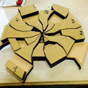
The right consists of 12 stage photos & these do not correspond directly with the stages listed in the document download. They are provided to show a fairly meaningful development process as the construction progressed from many small parts, all the way to a fully formed product.
Stage 1 - One of the thin top layers being cut, along with the laser cut numbers on a rectangular board.
Stage 2 - Tasmanian Oak veneer, this is what's placed on the very top below the numbers.
Stage 3 - A 3D cutting service was utilised in order to have the desired MDF shapes cut.
Stage 4 - A 3D cutting service was utilised in order to have the bottom MDF layer cut as desired.
Stage 5 - The cut MDF pieces.
Stage 6 - Placing the Tasmanian oak veneer pieces on top for the first time to ensure everything looks just right..
Stage 7/8 - Initially the plan was to have the metal strips laser cut as 1 piece, but unfortunately, that would've cost thousands, so, many many little pieces was the only way to go! The margin for error was not very forgiving, due to the tight spaces...
Stage 9 - A 3D cutting service was utilised in order to have the bottom MDF layer cut as desired. As can be seen in the middle, this is the placement for the functionality of the clock itself !
Stage 10 - The bottom part needs to contrast from the majority of the design, so black paint was applied to it, and masking tape was placed strategically because otherwise the black paint would have the potential to lessen the ability to stick parts onto the bottom part reliably..
Stage 11 - Many more metal parts have been applied!
Stage 12 - Adding the metal parts is almost complete, the next stage will be to finally add the glass panes.
Multiple Piece Tracking
The need to put many many pieces together was an absolute monstrous task! It was very daunting to know the margin for error was really small, so it was absolutely paramount to have visual documentation for keeping track of all this...


